This standard is issued under the fixed designation A 254; the number immediately following the designation indicates the year oforiginal adoption or, in the case of revision, the year of last revision. A number in parentheses indicates the year of last reapproval. Asuperscript epsilon (e) indicates an editorial change since the last revision or re-approval.
1. Scope
1.1 This specification covers double-wall, copper-brazed steel tubing suitable for general engineering uses, particularly in the automotive, refrigeration, and stove industries for fuel lines, brake lines, oil lines, heating and cooling units, and the like.
1.2 The values stated in inch-pound units are to be regarded as the standard.
2. Referenced Documents
2.1 ASTM Standards:
A 370 Test Methods and Definitions for Mechanical Testing of Steel Products2
E 30 Test Methods for Chemical Analysis of Steel, Cast Iron, Open-Hearth Iron, and Wrought Iron3
E 59 Practice for Sampling Steel and Iron for Determination of Chemical Composition
2.2 Society of Automotive Engineers Standard:
J 533 Flares for Tubing
3. Ordering Information
3.1 Orders for material under this specification should include the following, as required to describe the desired material adequately:

3.1.1 Quantity (feet, metres),
3.1.2 Name of material (copper-brazed steel tubing),
3.1.3 Type, where necessary (see Fig. 1) (normally the type is not specified),
3.1.4 Size (outside diameter and wall thickness; normally inside diameter should not be specified),
3.1.5 Length (specific or random),
3.1.6 Inside surface cleanliness where required (see Section 8),
3.1.7 External coating, where required (see Section 7 and Supplementary Requirement S2), and
3.1.8 Special or supplementary requirements or exceptions to specification.
4. Manufacture
4.1 The steel may be made by any process.
4.2 If a specific type of melting is required by the purchaser, it shall be as stated on the purchase order.
4.3 The primary melting may incorporate separate degassing or refining and may be followed by secondary melting, such as electroslag remelting or vacuum-arc remelting. If secondary melting is employed, the heat shall be defined as all of the ingots remelted from a single primary heat.
4.4 Steel may be cast in ingots or may be strand cast. When steel of different grades is sequentially strand cast, identification of the resultant transition material is required. The producer shall remove the transition material by an established procedure that positively separates the grades.
4.5 The tubing shall be made by rolling steel strip into the form of tubing and subsequently copper brazing in a reducing atmosphere.
4.6 Tubing shall be constructed as shown in Fig. 1.
4.7 Tubing shall be suitably tested after brazing by the manufacturer to ensure freedom from leaks and detrimental flaws.
5. Chemical Composition
5.1 The steel shall conform to the requirements as to chemical composition prescribed in Table 1.
TABLE 1 Chemical Requirements
| Element | Composition, % |
| Carbon | 0.05 to 0.15 |
| Manganese | 0.27 to 0.63 |
| Phosphorus, max | 0.035 |
| Sulfur, max | 0.035 |
5.2 Heat Analysis—An analysis of each heat of steel shall be made by the steel manufacturer to determine the percentages of the elements specified. If secondary melting processes are employed, the heat analysis shall be obtained from one remelted ingot or the product of one remelted ingot of each primary melt. The chemical composition thus determined, or that determined from a product analysis made by the tubular product manufacturer shall conform to the requirements specified.
5.3 Product Analysis—Tubing of this quality is commonly produced in rimmed or capped steel which is characterized by a lack of uniformity in its chemical composition. For this reason, rejection for product analysis is not appropriate unless misapplication is clearly indicated.
5.4 Methods of Analysis—Methods described in Test Methods E 30 shall be used for referee purposes. Due allowance shall be made for the presence of copper brazing metal.
5.5 Samples for Product Analysis—Except for spectrographic analysis, samples shall be taken in accordance with Practice E 59.
6. Mechanical Requirements
6.1 Tension Test—Tensile properties of tubing as manufactured (prior to cold working) shall conform to the requirements specified in Table 2.
6.1.1 The specimens and tension tests required shall be made in accordance with Test Methods and Definitions A 370.
6.1.2 Specimens shall be tested at room temperature.
6.1.3 Test specimens shall be taken from the ends of finished tubes prior to upsetting, swaging, expanding, or other forming operations, or being cut to length. They shall be smooth on the ends and free from burrs and flaws.
6.1.4 If any test specimen shows flaws or defective machining, it may be discarded and another specimen substituted.
6.1.5 The yield strength shall be determined as that corresponding to a permanent offset of 0.2 % of the gage length of the specimen, or a total extension of 0.5 % of the gage length under load.
6.1.6 If the percentage of elongation of any test specimen is less than that specified and any part of the fracture is more than 3⁄4 in. (19.0 mm) from the center of the gage length, as indicated by scribe marks on the specimen before testing, a retest shall be allowed.
TABLE 2 Tensile Requirements
| Property | Requirement |
| Tensile strength, min, psi (MPa) | 42 000 (290) |
| Yield strength, min, psi (MPa) | 25 000 (172) |
| Elongation in 2 in. (50.8 mm) min, % | 25 |
6.2 Flattening Test—A section of tubing, not less than 21⁄2 in. (64 mm) in length, shall stand being flattened between parallel plates until the inside walls are in contact without cracking or otherwise showing flaws.
6.3 Expansion Test—A section of tubing approximately 4 in. (100 mm) in length shall stand being expanded over a tapered mandrel having a slope of 1 in 10 until the outside diameter at the expanded end is increased 20 % without cracking or otherwise showing flaws. (Prior to the expansion test, tubing shall be cut off square, edge crowned, and deburred. It shall be held firmly and squarely in the die, and punch must be guided on the axis of the tubing.)
6.4 Bend Test—The finished tubing shall stand bending on a centerline radius equal to three times the tubing outside diameter without kinking, cracking, or developing other flaws where proper bending fixtures are used.
6.5 Pressure Proof Tests—Each tube shall be capable of withstanding, without bursting or leaking, either of the following proof tests:
6.5.1 An internal hydrostatic pressure sufficient to subject the material to a minimum fiber stress of 16 000 psi (110 MPa). Hydrostatic pressure shall be determined by the following
formula:
P 5 2St/D
where:
P = hydrostatic pressure, psi (or MPa),
S = allowable fiber stress, 16 000 psi (110 MPa),
t = actual wall thickness of tubing, in. (or mm), and
D = actual outside diameter of tubing, in. (or mm).
6.5.2 An underwater air pressure between 225 and 250 psi (1.55 and 1.73 MPa).
7. Coating
7.1 Tubing may be furnished with a copper coating on the inside and outside surfaces, at the option of the manufacturer.
8. Inside Surface Cleanliness
8.1 When inside surface cleanliness is specified by the purchaser, tubing for certain uses, such as refrigeration condensers, shall conform to the following requirement for internalcleanliness:
8.1.1 When a length of tubing is washed internally with redistilled chloroform or redistilled 1,1,1-trichloroethane, the residue remaining upon evaporation of the solvent shall not exceed 1.25×10⁻⁴ g/in.2(0.194 g/m2) of internal surface. To perform the test, pour 100 mL of solvent through the tubing and collect. The total length of tubing tested should not be less than 40 ft (12 m), although this total length may be obtained by washing several separate lengths and pouring the same solvent through each in succession. Evaporate the solvent in a steam or hot water bath, and dry at 110°C (230°F) until the vapors are completely removed.
8.2 To maintain this level of cleanliness in shipping, handling, and storage, the purchaser may request that the manufacturer seal the tube ends with caps or closures.
9. Dimensional Tolerances
9.1 The tubing shall conform to the permissible variations in Table 3, Table 4, and Table 5.
10. Workmanship, Finish, and Appearance
10.1 Finished tubing shall be clean, smooth and round, both inside and outside, and shall be free of rust, scale, and defects that impair processing and serviceability. Finished tubes shall
be reasonably straight.
TABLE 3 Outside Diameter Requirements
| Specified Outside Diameter, in. (mm) | Variations, in. (mm) |
| Plus or Minus | |
| Under 3⁄16 (4.76) | 0.002 (0.051) |
| 3⁄16 (4.76) through 3⁄8 (9.53) | 0.003 (0.076) |
| 7⁄16 (11.1) through 5⁄8 (15.9) | 0.004 (0.102) |
TABLE 4 Wall Thickness Requirements
| Specified Wall Thickness, in. (mm) | Variations, in. (mm) |
| Plus or Minus | |
| 0.020 (0.51) through 0.030 (0.76) | 0.003 (0.08) |
| 0.031 (0.79) through 0.049 (1.24) | 0.0035 (0.09) |
TABLE 5 Length Requirements
| Specified Cut Length, in. (m) | Variations, in. (mm) |
| 18 (0.46) and under | ±0.03 (±0.76) |
| Over 18 (0.46) through 40 (1.02) | ±0.06 (±1.52) |
| Over 40 (1.02) through 80 (2.03) | ±0.12 (±3.05 ) |
| Over 80 (2.03) through 120 (3.05) | ±0.25 (±6.35 ) |
| Over 120 (3.05) | +1.00 (+25.4), −0.0 |
11. Retests
11.1 If the results of the mechanical tests of any group or lot do not conform to the requirements specified in the individual specification, retests may be made on additional tubes of double the original number from the same group or lot, each of which shall conform to the requirements specified.
12. Retreatment
12.1 If the individual tubes or the tubes selected to represent any group or lot fail to conform to the test requirements, the individual tubes or the group or lot represented may be retreated and resubmitted for test. Not more than two reheat treatments shall be permitted.
13. Inspection
13.1 The inspector representing the purchaser shall have entry at all times while work on the contract of the purchaser is being performed, to all parts of the manufacturer’s works that concern the manufacture of the material ordered. The manufacturer shall afford the inspector all reasonable facilities to satisfy him that the material is being furnished in accordance with this specification. All required tests and inspection shall be made at the place of manufacture prior to shipment, unless otherwise specified, and shall be conducted so as not to interfere unnecessarily with the operation of the works.
14. Rejection
14.1 Each length of tubing received from the manufacturer may be inspected by the purchaser and, if it does not meet the requirements of the specification based on the inspection and test method as outlined in the specification, the tubing may be rejected and the manufacturer shall be notified. Disposition of rejected tubing shall be a matter of agreement between the manufacturer and the purchaser.
14.2 Material that fails in any of the forming operations or in the process of installation and is found to be defective shall be set aside, and the manufacturer shall be notified for mutual evaluation of the material’s suitability. Disposition of such material shall be a matter for agreement.
15. Certification
15.1 When requested on the purchaser’s order, a test report, signed by an authorized employee or representative of the manufacturer, shall be furnished to the purchaser to indicate the specification and year date and grade, the results of the chemical analysis, hardness, and tension tests, when specified, and other tests as may be specified in writing by the purchaser.
16. Product Marking
16.1 The specification number (the marking need not include the year date of the specification), the name or brand of the manufacturer and the size of tubing or the part number shall be marked on a tag or label securely attached to the bundles or boxes in which the tubes are shipped.
16.2 Bar Coding—In addition to the requirements in 16.1 bar coding is acceptable as a supplemental identification method. The purchaser may specify in the order a specific bar coding system to be used.
SUPPLEMENTARY REQUIREMENTS
One or more of the following supplementary requirements shall apply only when specified by the purchaser in the inquiry, contract, or order. Details of these supplementary requirements shall be agreed upon by the manufacturer and the purchaser.
S1. Flare Test
S1.1 Brazed tubing shall stand being double flared to dimensions shown in SAE Standard J 533, without splitting through the wall at the major diameter of the flare. Aseparation of the outer lap joint is permissible on the flared end of the tube only in Area A (see Fig. S1.1). This separation shall not exceed 0.12 in. (3.0 mm) in length and shall be confined to the outer thickness only. Seam separation is not permitted in the following areas:
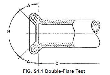
S1.1.1 Area B (the flare seat, defined as the surface within the 90° included angle); conical surface shall be smooth and free from cracks or other irregularities that could cause leaks after assembly.
S1.1.2 Area C (the surface beyond the length of the double thickness created by the flare).
S1.2 The flare seat may contain superficial random radial marks or indentations which are not detrimental to the sealability of the flare. No indentations of a repetitive nature resulting from flaring tooling deterioration or adhesion of chips or dirt to the flaring tooling are permissible. In the event that the physical appearance of the flare seat is questioned, the criterion for final judgment is whether or not the flare seat will seal when subjected to a pressure test at the prescribed torque level.
S2. External Coating
S2.1 The outside surface of the tubing shall be coated with a hot-dipped, lead-tin alloy coating.Weight and composition of coating shall be agreed upon between the manufacturer and purchaser.
S3. End Finish
S3.1 Finished tubing shall have smooth ends free of burrs.